Sea turtle robot
- Role
- Umbilical and mechatronics lead
- Team
- Five engineers in one subassembly group
I led the umbilical and mechatronics work on a robotic sea turtle. I built the Simulink model of its variable-buoyancy depth control and tuned the PID controller.
Result
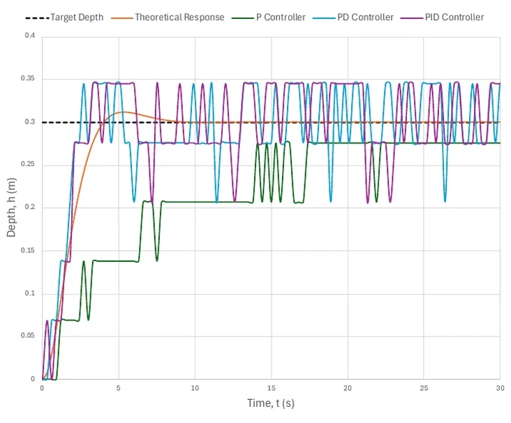
In a tank test of the buoyancy tube, PID control settled in 4.5 s against 11.5 s for P control
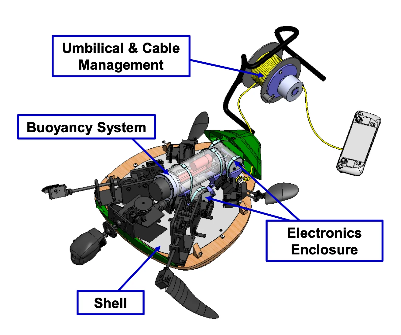 Assembly CAD
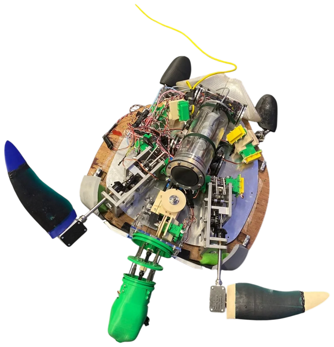 Built prototype, shell removed
Problem
The robot changes depth with a variable-buoyancy cylinder: a linear actuator moves a diaphragm, which changes the volume of water the cylinder displaces. My job was to close the loop, so the robot holds a commanded depth on its own.
Design
The buoyancy cylinder sits inside the shell, tilted under its arch. The two round electronics enclosures sit low in the hull beneath it, and the umbilical leaves the robot to a reel at the surface.
I modelled the buoyancy tube in Simulink as a single body moving vertically, with an effective mass and linear hydrodynamic damping. The loop runs from the depth error through the controller, motor driver and actuator to the diaphragm, and back through the pressure sensor. I tuned the gains with the Ziegler–Nichols method: raising a proportional gain until the depth response oscillated steadily, then calculating the PID gains from that gain and the oscillation period.
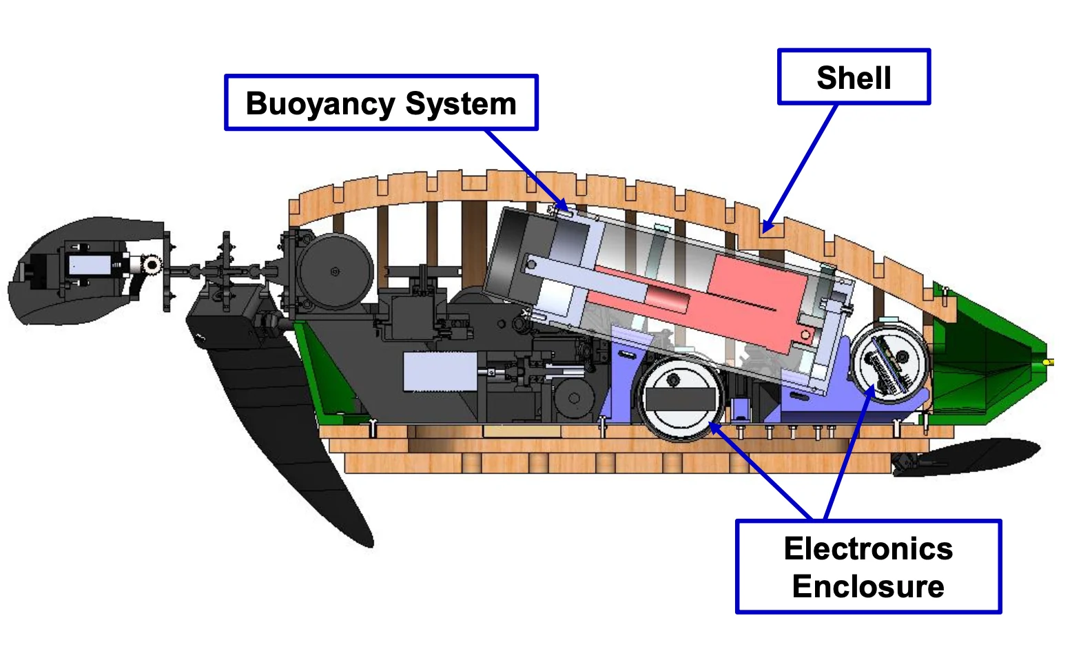 Side section through the robot
Before closing the loop, the group measured what the actuator can do. Over three extension and retraction cycles, the cylinder produced 6.45 ± 0.60 N of buoyancy force at 50 mm of diaphragm displacement.
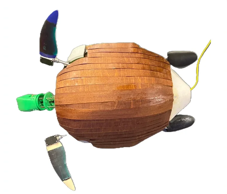 The built robot, from above
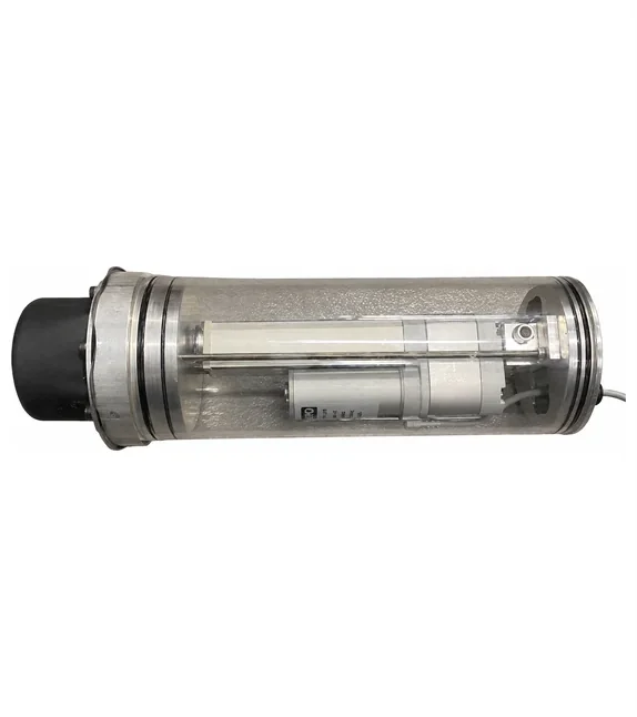 The variable-buoyancy cylinder
Testing and results
Two tests set up the results: a calibration of the depth sensor, then the closed-loop control test on the buoyancy tube.
Pressure sensor calibration
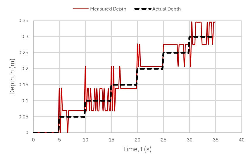
The depth reading comes from a pressure sensor, so the group checked the sensor on its own first, before any control. We held the sensor against a ruler and lowered it through the tank in 5 cm steps from 0 to 30 cm, letting the reading settle at each step. The sensor tracked depth, but in steps: its reported resolution was 0.069 m, and the maximum measurement error was approximately ±0.069 m.
- Transient spikes while the sensor was being moved
- Quantisation: readings step between levels 0.069 m apart
Measured depth against the actual depth as the sensor was lowered in 5 cm steps. Pressure sensor calibration, from the group's testing.
The spikes are local pressure disturbances from moving the sensor through the water; they settle once it stops. The quantisation stays, and it shapes the control results below.
Closed-loop depth control
This test ran the controllers on the buoyancy tube by itself, not on the assembled robot. The tube was front-heavy and pitched forward once submerged, so we tied a counterweight to its rear to keep it close to level. Each controller started at the surface with a 0.30 m depth command.
| Controller | Rise time | Overshoot | Settling time | Steady-state error |
|---|---|---|---|---|
| P | 6.0 s | 0% | 11.5 s | 0.024 m |
| PD | 2.7 s | 12% | 5.0 s | 0.015 m |
| PID | 2.4 s | 8% | 4.5 s | 0.010 m |
From P to PID, rise time fell from 6.0 s to 2.4 s and settling time from 11.5 s to 4.5 s. Adding the derivative term cut settling time the most; the integral term then brought the reported steady-state error down from 0.015 m to 0.010 m.
The measured depth switches between neighbouring levels around the setpoint, and the calibration explains why: the sensor can only report depth in 0.069 m steps, so the controller keeps switching while the true depth stays close to the setpoint. The 0.010 m figure is the reported error used to compare the three controllers in this test. It is finer than the sensor’s resolution, so it isn’t the assembled robot’s depth accuracy.
What I’d change
A finer pressure sensor first: its resolution, not the controller, limits how steadily the robot can hold depth. I’d also add a deadband around the setpoint, so the actuator stops chasing quantisation steps and the motor driver runs cooler.