Gibbon rope bridge
- Role
- Transmission engineer
- Team
- Five engineers
I was the transmission engineer on a 1:10 gibbon canopy-bridge prototype for Imperial's Build the Change project with New Scientist and The LEGO Group. I designed the hand-cranked transmission that tensions the rope, and kept the team's timeline.
Result
A hand-cranked, two-shaft tensioner with a 3.33:1 gear reduction, for a 1:10 prototype bridge
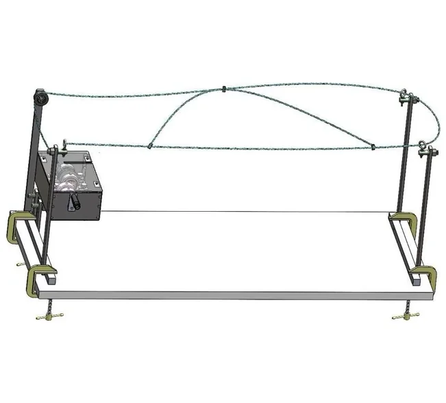 The 1:10 prototype bridge, in CAD
Problem
Roads through rainforest cut off the canopy that gibbons travel through. The brief was a rope bridge that lets them cross safely, built as a 1:10 prototype, with a safety factor of at least 1.5 on every component and a £300 budget. The team’s first concept was a static bridge fixed between trees. Midway through the design phase the brief added a transmission requirement, so we turned it into a bridge tensioned by hand from a winch at the base of a tree.
Design
The transmission is two shafts in pillow-block bearings inside a steel casing. The power path runs:
- The hand crank turns Shaft 1.
- Shaft 1’s 12-tooth gear drives the 40-tooth gear on Shaft 2.
- Shaft 2 turns a U-grooved drum that winds the rope in.
That gives a 3.33:1 reduction from crank to drum. Each shaft runs in one fixed and one floating bearing. M3 set screws hold the gears and the drum on their shafts, which is enough at these torques, and 12 mm circlips locate Shaft 1 in its bearings.
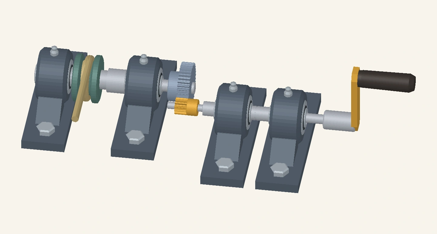
12-tooth input gear. Fixed to Shaft 1 with the hand crank, so it turns once per crank turn.
40-tooth output gear. On Shaft 2. Driven by the 12-tooth gear, it turns the opposite way and 3.33 times slower: 108° for each crank turn.
U-grooved rope drum. Also on Shaft 2, between its two bearings. Its deep U groove stores the rope as the drum winds it in, which tensions the bridge.
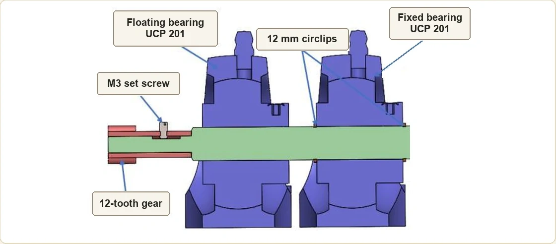 Shaft 1: input gear and bearings Open Shaft 1 section
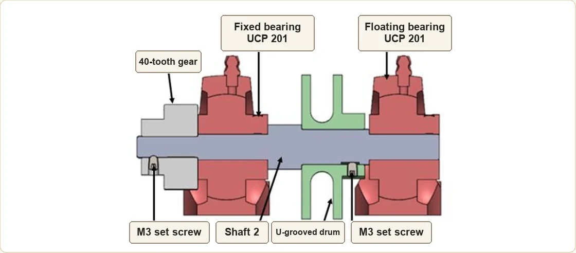 Shaft 2: output gear and rope drum Open Shaft 2 section
The first arrangement didn’t fit the casing. During CAD we flipped the output shaft over so the gears lined up in the space available, and moved the crank to suit.
Testing and results
This write-up covers the design. The team’s design report was written before the prototype’s final performance test.