Conveyor drive transmission
I designed a two-stage drive for a roller conveyor feeding steel strip into a chain-link production line.
Result
An 8.21:1 two-stage drive taking a 2,910 rpm motor to 355 rpm at the roller (design values)
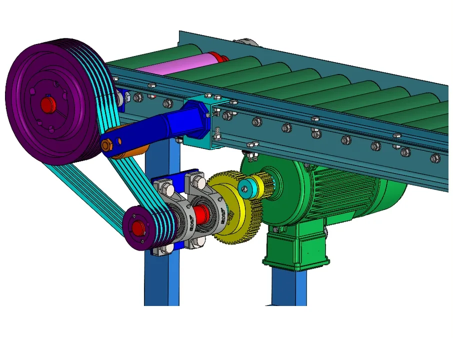 Drive side, in CAD
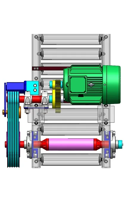 From underneath
Problem
The conveyor feeds flat steel strip to a press that makes 110 chain links a minute. Its driven roller has to turn at 355 rpm on average while feeding, from a 9 kW motor running at 2,910 rpm, for a service life of 20,000 hours.
Design
The drive reduces speed in two stages. All the figures here are design values from the briefing, not measurements.
| Stage | Elements | Ratio |
|---|---|---|
| 1 | Spur gears, module 3, 20 to 58 teeth | 2.90:1 |
| 2 | V-belt, 106 mm to 300 mm pulleys | about 2.83:1 |
| Overall | 8.21:1 |
That takes the motor’s 2,910 rpm to 355 rpm at the driven roller, with 242.1 N·m on the output shaft. An idler tensioner keeps the belt tight.
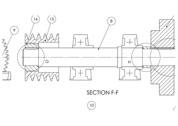
The intermediate shaft is where the two stages meet, and it shows how each part is held. One bearing is fixed and the other floats, so the shaft can grow with temperature without loading the bearings end-on.
- 106 mm pulley on a keyed taper bush, against a shoulder
- Floating bearing: free to slide as the shaft grows
- Fixed bearing: inner ring held by a shoulder and a spacer
- 58-tooth gear: keyed, held by an end cap and spacer
The intermediate shaft in CAD, sectioned. The assembly drawing, not the CAD, controls dimensions and fits.